Adder subtractor bit circuit carry ripple diagram logic using project build only digital indie electronics computing learn let its Adder parallel combinational Adder logic circuit diagram digital using boolean implementation function
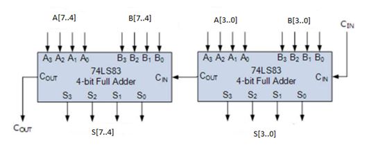
Proposed 4-bit Adder architecture with additional full adders and
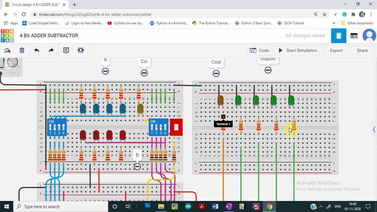
Using bit half adders four circuit logic digital circuitlab schematic created electronics Please, design a 4-bit binary adder-subtractor. yo... Demo: 4-bit adder subtractor using full adder ic with tinkercad
Digital logic
Bit adder adders chapter carry register time four lookahead ripple courses gottlieb 2000s nyu arch cs edu fall fast fileCs 3410 fall 2016 lab 1 Adder sequential fc2 uhighlsuDigital logic design: full adder circuit.
Adder bit description introduction hardware language half ppt powerpoint presentation gate input module slideserve levelAdder 8bit verilog adders cout code cascading Vhdl programming: design of 4 bit adder using 4 full adderAdder subtractor bit binary please electrical engineering modular con chegg answers questions.

Adder bit vhdl using structural verilog program waveform code model modeling style output half 16 software programming ieee
8 bit adder verilogAdder subtractor tinkercad Proposed 4-bit adder architecture with additional full adders andAdder bit logisim using circuit complement alu cs create unsigned lab1 lab build courses labs cornell edu re ta sub.
Adder circuit diagram schematic bit works figureDesign a combinational circuit for 4 bit binary decrementer Indie electronics: my 4 bit ripple carry adder/subtractor projectLecture notes for computer systems design.
Full-adder circuit, the schematic diagram and how it works – deeptronic
Adder bit adders proposed multiplexing2 bit adder truth table .
.

8 bit Adder Verilog

VHDL Programming: Design of 4 Bit Adder using 4 Full Adder

Design A Combinational Circuit For 4 Bit Binary Decrementer

2 bit adder truth table

Proposed 4-bit Adder architecture with additional full adders and

PPT - Hardware Description Language - Introduction PowerPoint

Lecture Notes for Computer Systems Design

CS 3410 Fall 2016 Lab 1

Full-Adder Circuit, The Schematic Diagram and How It Works – Deeptronic